Features
- Interfaces 48 general purpose digital I/Os to Ethernet
- Each channel can function as input, output, or wired-OR
- PWM output mode
- Input debounce filters
- Directly connects to field wiring
- Integrated support for safety interlocks
- Selectable operating voltage per channel
- Connects to Ethernet through 2601
- DIN-3 rail mountable
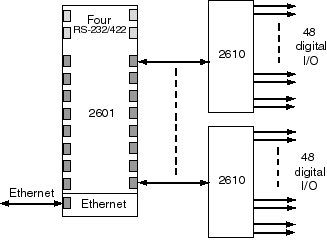
Model 2610 is a modular, 48 channel digital I/O interface that connects to Ethernet through a 2601 communication module. It has 48 general-purpose digital I/O channels that can independently serve as inputs, outputs, or in wired-OR mode. It is a member of the 2600 series of smart I/O modules.
All 48 channels support standard, programmed output operation, and 32 channels also support PWM (pulse width modulated) output operation, which is useful for controlling motors, heaters, and similar devices. Input signals are passed through a 10 millisecond debounce filter to prevent errors from electromechanical switch bounce. The physical state of each I/O line is indicated with a LED so that signal states can be quickly determined by visual inspection.
Multiple 2610 modules can be connected to a single 2601

The 2610 can be connected to any of the sixteen IOM (I/O module) ports on a 2601. This is done with a low-cost category-5 patch cable, which supplies communication signals and logic operating power to the 2610. A 2600C1 daisy-chain power cable is also required, to supply I/O power and route interlock signals to the module.
Field Wiring
Field wiring can be directly connected to the module's 48 RJ-11 sockets — no external termination boards are needed. Each socket provides connections to as many as three I/O channels, making it possible for a field cable to convey up to three active signals through a single socket.
I/O Power and Interlock System
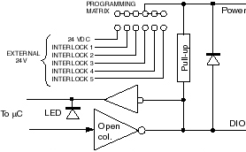
Up to five different I/O voltages can be supplied to the 2610 through its interlock connector. A second, identical interlock connector is provided so that I/O power can be conveniently daisy-chained to other modules, thus eliminating the external wiring and termination boards that would otherwise be required. Each digital output can be configured to use any I/O supply voltage.
A shunt selects each channel's I/O power source

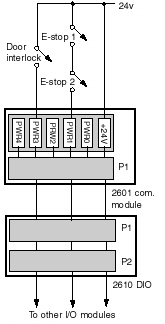
The I/O supply voltages may be continuous or, if desired, they may be interruptible by external, series-wired contacts (e.g.,interlock, emergency-stop). If a supply voltage is interrupted due to an open contact, all associated outputs will automatically turn off, independent of software operation.
Interlock example

Specifications
| Digital I/Os |
|---|
| Number |
48 |
| Voltage range |
+5 to +24 VDC (supplied through interlock connector) |
| Output type |
Open collector |
| Output sink current (maximum) |
100 mA, per channel
2000 mA, all channels total |
| Input sink current (maximum) |
600 µA |
| PWM on/off time |
2 to 510 ms in 2 ms steps |
| Input debounce period |
10 ms |
| Connector type |
RJ-12 |
| Communications |
|---|
| Commands per second |
Up to 1000 |
| Power |
|---|
| Input power |
24 VDC, 120 mA (no output loads) |
| Mechanical |
|---|
| Module dimensions |
(W x H x D): 14.25 x 4.93 x 1.87 inches; 362 x 125 x 47.5 mm |
| DIN rail |
35 mm DIN rails |
| Environmental |
|---|
| Operating temperature range |
20 to 70 °C |
A variety of I/O module types are available, each with a specialized function: